

RM6 user guide
Everything you need to get a Remotii RM6 wired, on your Wi-Fi and into your account - and what to do when you need to start again.
What is on the unit
- Two lights. The green light shows what your inputs and outputs are doing. The red light shows whether the unit is connected to Remotii.
- The setup button, behind a small hole in the end of the case, beside the USB-C socket. Press it with the end of a straightened paperclip. It is recessed on purpose so it cannot be pressed by accident. Its one job is the factory reset.
- Power. 8-30 V DC on the power terminal at the end of the case, or 5 V from a USB-C charger rated for at least 2 A. See Power.
- Screw terminals along both long edges for your wiring, 5 mm apart. A small flat screwdriver (a 3 mm blade) reaches them with the lid on. Each takes one wire, 14 to 22 AWG. See Wiring.
Mounting
The case hangs on two screws through the keyhole slots in its back, either way up. Vertical: the power terminal and USB-C at the bottom, so the cables drop straight down. Level: the Remotii logo on the lid upright, with the power on the right. Use two #8 or M4 pan-head screws, 60 mm apart - on a level line for a level hang, one directly above the other for a vertical one - and leave each head standing 2 to 3 mm off the wall. Offer the case up over both heads and slide it down until it stops. Keep the end away from the power terminal clear of metal: the Wi-Fi antenna is behind it.
Print the mounting stencil
The mounting stencil (PDF) marks exactly where to drill. Print it at Actual size (100 %) - its two bars must measure 50 mm and 2 in - and cut it out: it is the case's outline, true size, as seen from the front. Drill the two H marks (navy, solid) for a level hang, or turn the sheet a quarter turn and drill the two V marks (red, dashed) for a vertical one. Check the line with a spirit level before you drill. The same stencil is on the page that prints with the unit's label on plain paper.
The unit's label (its claim code and QR code, web login, device id and MAC address) comes loose in the box. Stick it on the recessed pad on the back, somewhere else that suits, or nowhere. The claim card in the box carries the same claim code: keep it, or hand it to the unit's owner, so the unit can be added to an account after it is on the wall.
What the lights mean
Red light: the connection to Remotii
| The red light is | What it means |
|---|---|
| Off | Connected to Remotii. Everything is working. |
| A short wink every two seconds | Not connected yet since it was switched on. It is still joining your Wi-Fi or reaching Remotii. This is normal for the first minute after power-up. |
| On steadily | It was connected, and has lost the connection. It keeps trying by itself. |
The red light is about the connection to Remotii, not just your Wi-Fi. A unit that has joined your Wi-Fi but cannot reach the internet keeps its red light winking or lit.
Green light: your inputs and outputs
The green light repeats the same pattern over and over:
- A two-second pause with the light off.
- For each input that is on, it blinks that input's number: once for input 1, twice for input 2, and so on, with a short pause after each.
- A burst of twelve fast flickers, which separates the inputs from the outputs.
- For each output that is on, it blinks that output's number the same way.
With nothing on, you see only the fast flicker every few seconds - that tells you the unit is running. The green light keeps doing this whether the unit is online or not, so you can check your wiring at the unit with no phone or laptop. It covers the four on/off inputs and the outputs; the analog and temperature inputs are not shown on the light.
While you hold the setup button, the green light changes to a countdown instead - see Factory reset.
Both lights on steadily: the setup network is open
When the unit opens its own setup network (see Connecting to Wi-Fi), both lights stay on steadily for as long as that network is open - on a new unit, that is straight away. It is not a fault: it means there is a Remotii-xxxx network to join. The lights go back to their usual patterns once the setup network closes. Holding the setup button still shows the reset countdown, even while both lights are on.
Connecting to Wi-Fi
You do not need to press anything to start Wi-Fi setup. The unit opens its own setup network by itself when it needs one:
- Straight away, when it has no Wi-Fi network saved - a new unit, or one that has just had a factory reset.
- After about 3 minutes without its saved network - for example after you change your router or its password. It keeps trying the old network the whole time, so if that comes back, the unit rejoins by itself.
The setup network is called Remotii-xxxx, where xxxx is four letters and numbers that belong to your unit. It has no password. While it is open, both of the unit's lights are on steadily.
- Join the setup network. On your phone or laptop, open the Wi-Fi settings and choose Remotii-xxxx.
- Open the unit's page. Most phones open the sign-in page on their own. If yours does not, open a browser and go to http://192.168.4.1.
- Sign in. The user name is admin, already filled in. The password is the unit's factory password, printed on its label. Every unit has its own.
- Choose your own password. The unit takes you straight to Change the password. Wi-Fi settings stay locked until you do this - see why. Use at least 8 characters. You are then signed out, so sign in again with the new password.
- Pick your network. Go to Network and press Scan. Choose your network from the list (or type its name), enter its password and press Join.
- Check it worked. The Network page shows Station: up with an address when the unit has joined.
The setup network stays open while your phone is still connected to it, so you can watch the result, and both lights stay on until it closes. Once you disconnect, the unit closes it within a minute or so and carries on on your own network: the lights go back to their usual patterns, and when the red light goes off the unit has reached Remotii and you are done. From then on you reach its page at http://remotii-xxxx.local - see below.
If the setup network is open and nobody finishes setup, anybody nearby could join it. That is why the unit refuses to change its Wi-Fi settings until its factory password has been replaced.
The unit's own web page
The unit has its own small web page. It works on your local network all the time, not just during setup, and it does not need the internet - handy for checking an input at the unit itself.
Where to find it
| Address | When it works |
|---|---|
| http://remotii-xxxx.local | Any time, from a phone or computer on the same network as the unit. xxxx is the same four characters as in its setup network's name. |
| http://the unit's IP address | Any time. Your router's list of connected devices shows it. Use this if the .local name does not open - some Windows computers cannot look those names up. |
| http://192.168.4.1 | Only while you are connected to the unit's setup network. |
The address starts with http, not https. That is expected for a device on your own network; nothing on the page leaves your network.
Signing in
The user name is always admin. A new unit, and any unit after a factory reset, uses its factory password, which is printed on the unit's label. Each unit has a different one. After 5 wrong passwords in a row the page stops accepting sign-ins for 30 seconds. A sign-in lasts 12 hours, or until the unit restarts.
Changing the password
Change the factory password even so: it is printed on a label that anybody who handles the unit can read. Until you do, the page shows a reminder at the top and Wi-Fi settings are locked: joining a network is the moment the unit becomes reachable by other people, so that is where the password has to be yours. Everything else - checking inputs, switching outputs - works with the factory password, so a technician is never held up.
The first time you sign in with the factory password, the page takes you straight to Change the password. Type the new password once - it does not ask for the factory password again, or for the new one twice. Later, to change it again, go to Settings, then Change the web password: this time the page asks for your current password and the new one, once each, so somebody who finds a signed-in page left open cannot lock you out. A wrong current password counts towards the same 5-try limit as signing in. Tap the eye button beside a field to see what you typed before you save it (the sign-in page has the same button). The new password must be at least 8 characters and cannot be the factory password. Changing it signs everybody out, including you. If you forget it, a factory reset puts back the factory password on the label - and clears your Wi-Fi settings with it.
What the page offers
| Page | What it is for |
|---|---|
| Status | Whether each input is open or closed, and each output with On, Off and Pulse buttons (1 second pulse). Also the unit's network, address, signal strength, whether it is connected to Remotii, and its firmware version. Switching an output here shows up in the Remotii app as well. |
| Network | Scan for networks and join one. Shows which network is saved, whether the unit is on it, and whether the setup network is open. |
| Log | What the unit has been doing, newest first, with a button to download it as a text file for support. The log starts empty after each restart. |
| Settings | What each relay does when power comes back after a power cut (off, on, or back to how it was). Change the password, restart the unit, or factory reset it. |
| Claim | The unit's device ID and claim code, and a QR code that opens Remotii's claim page with the code already filled in. See the next section. |
Adding the unit to your account
Adding a unit to your Remotii account is called claiming it, and it takes the unit's claim code.
- Get the unit online first (see Connecting to Wi-Fi). That way it shows up in your account already working. The red light is off once the unit has reached Remotii.
- Find the claim code. It is printed on the unit's label, and it is also on the Claim page of the unit's own web page - the same code in both places: 6 capital letters and numbers. The letters I, L, O and U are never used, so an O is always a zero.
- Claim it. Scan the QR code on the label or on the Claim page with your phone: it opens Remotii's claim page with the code filled in (sign in first if it asks; the code is kept). Or sign in to Remotii (or register), go to Devices, choose Add a device and type the code. Give the unit a name if you like, and press Add to my home.
The unit then appears in your account straight away. A unit can only be claimed once: after that its code no longer works for anybody else.
A factory reset does not change the claim code: the code on the label keeps working until the unit is claimed.
Factory reset
A factory reset puts the unit's own settings back to how they were when it was new. Use it when you have moved the unit to a different network and cannot reach its page, or have forgotten its web password.
With the setup button
- With the unit powered, push a straightened paperclip straight into the small hole beside the USB-C socket until you feel the button press.
- Hold it for 10 seconds. The red light goes out and the green light counts down, slowing as it goes - quick blinks at first, fewer and slower each second, down to one slow blink in the last second.
- When both lights flash together three times, the reset has happened and the unit restarts by itself. Let go of the button. Once it is back up, both lights stay on steadily: it is waiting to be set up on Wi-Fi again.
Let go before the countdown finishes and nothing happens - the lights go back to normal. Holding the button while you plug the unit in does nothing either; the unit only listens to the button once it has been released for a moment after power-up.
From the unit's web page
If you can still sign in, Settings has a Factory reset button that does the same thing, after asking you to confirm.
What a factory reset clears, and what it keeps
Cleared
- The saved Wi-Fi network and its password.
- Your password for the unit's web page - it goes back to the factory password printed on the label.
- What each relay does after a power cut, and any relay state it was holding for that - every relay goes back to off.
Kept
- The unit's identity - the security certificate that proves to Remotii which unit it is. It is stored separately and a factory reset never touches it, so the unit can reconnect as soon as it is back on Wi-Fi.
- Its place in your Remotii account. A reset does not remove the unit from your account.
- The claim code and the factory password on its label. They are stored with the identity.
- Everything you set up in the Remotii app - names, colours, rules, alerts, sharing. Those live in your account, not on the unit.
- Its firmware.
After the restart the unit has no Wi-Fi saved, so it opens its setup network straight away and both lights come on steadily. Follow Connecting to Wi-Fi from the top.
Wiring
Disconnect the unit's power, and the power to whatever you are connecting, before you wire it. Everything on these terminals is low voltage. The RM6 is not for mains wiring.
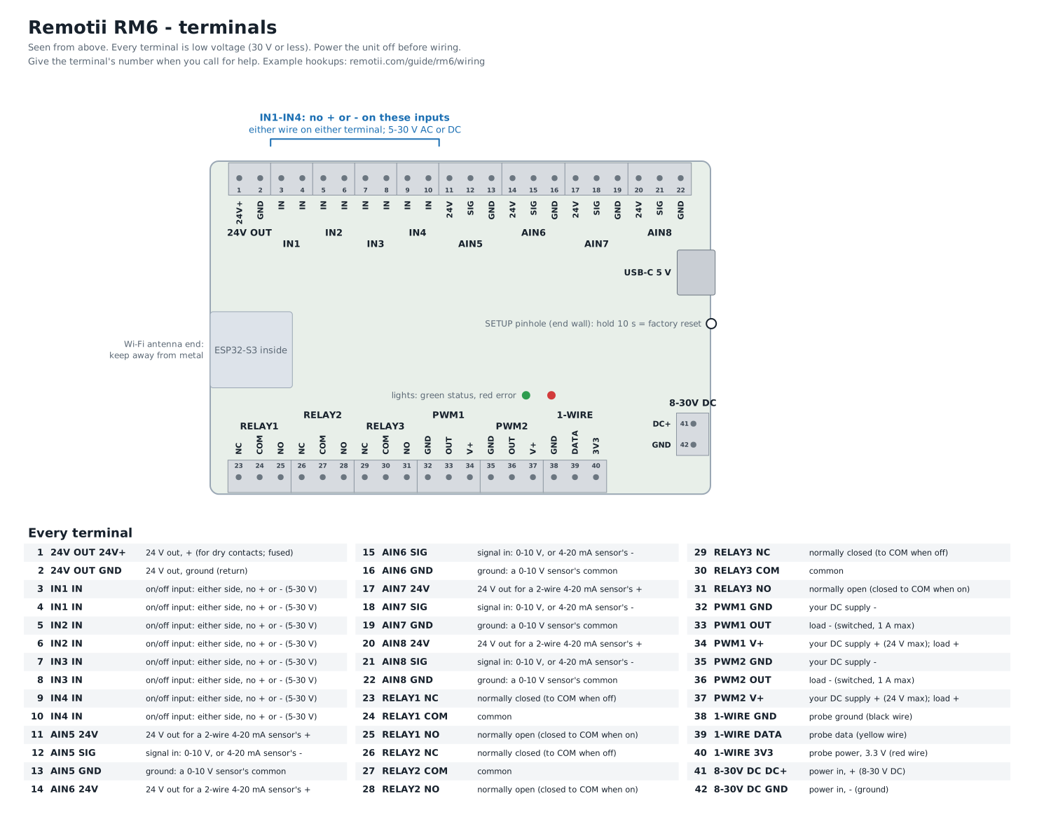
The names in the app
In the app each input and output is named after the terminal it is wired to, as printed on the unit and on the diagram, until you give it a name of your own. Its tile keeps showing the terminal under your name, so you can always find it on the unit.
| In the app | Terminals on the unit | What it is |
|---|---|---|
| IN1 to IN4 | IN1 to IN4 | On/off inputs (inputs 1 to 4) |
| AIN5 to AIN8 | AIN5 to AIN8 | Analog inputs, 0-10 V or 4-20 mA (inputs 5 to 8) |
| Temperature 1, 2, ... | 1-WIRE | Each DS18B20 probe on the 1-Wire terminals (inputs 9 upward) |
| RELAY1 to RELAY3 | RELAY1 to RELAY3 | Relays (outputs 1 to 3) |
| PWM1, PWM2 | PWM1, PWM2 | PWM outputs (outputs 4 and 5) |
On/off inputs (inputs 1 to 4)
Two terminals per input. An input is on when there is a voltage between its two terminals, and off when there is not. It accepts anything from 5 to 30 V, AC or DC, and it does not matter which way round the two wires go.
Each input is isolated: it is powered by the voltage you connect, and nothing on that side connects to the unit's own power or ground. So one unit can watch an alarm panel on 12 V and a control circuit on 24 V at the same time without joining them together.
A plain switch or relay contact (a door contact, a float switch, a "dry contact" output on an alarm panel) has no voltage of its own, so the RM6 provides one: the two terminals marked 24V OUT, at the start of the input row. Wire 24V OUT + to one side of the contact, the other side of the contact to one of the input's terminals, and the input's other terminal back to 24V OUT GND. The input turns on when the contact closes. One 24V OUT can feed dry contacts on all four inputs.
An input wired to 24V OUT shares the unit's ground. For an input that must stay isolated, wire it to your own 5 to 30 V supply instead, the same way.
Something that holds a signal while all is normal - an alarm panel output that pulls down while a door is closed, for example - reads on while things are normal. To have it read on when something happens instead, open the input in the Remotii app and tick Invert (units with firmware 1.10.6 or later). The unit itself flips the input, so its lights and its own web page agree with the app.
Analog inputs (inputs 5 to 8)
Three terminals per input: 24 V, signal and ground. Each one takes either a 0 to 10 V sensor or a 4 to 20 mA sensor. Which kind is a setting for that input in the Remotii app, and each input starts out set for 0 to 10 V, which is safe whatever is connected. Set the input before you rely on its readings.
- 4 to 20 mA sensor (two-wire). The unit powers it: sensor + to 24 V, sensor - to signal. You do not need a separate power supply for the sensor.
- 0 to 10 V sensor. Sensor output to signal, sensor common to ground.
In the app you can turn the reading into what the sensor actually measures - percent humidity, tank level, pressure - by entering the sensor's range. A 4 to 20 mA reading well below 4 mA usually means a broken wire, and the app shows it rather than hiding it.
The analog inputs are protected but not isolated. Keep analog sensors in the same building as the unit; a sensor in a different building, on a different electrical earth, needs an external isolator.
Relays (outputs 1 to 3)
Three terminals per relay: COM (common), NO (normally open) and NC (normally closed). When the relay is off, COM is connected to NC. When it is on, COM is connected to NO. Use COM and NO for something that should run only when switched on; use COM and NC for something that should stay on unless it is switched off, such as a fail-safe interlock.
The relay contacts are separate from everything else, so they act like a push button or switch wired into your own equipment - a garage door opener's button input, an alarm panel zone, a thermostat call, a gate controller.
Low voltage only: up to 30 V AC or DC - 1 A at up to 24 V DC, 0.5 A AC. These are signal relays. They are not for mains, motors, pumps or lighting - to switch something like that, use the RM6 relay to switch a properly rated contactor or relay.
PWM outputs (outputs 4 and 5)
Three terminals per output: V+, OUT and ground. These switch a load on and off rapidly to set its level - a DC fan's speed or an LED strip's brightness, for example. The unit does not power the load: connect your own DC supply + to V+ and - to ground, and connect the load between V+ and OUT. Each output switches up to 1 A from a supply of up to 24 V. Protection for motors and coils is built in and works against your supply, not the unit's.
In the app a PWM output has a switch like a relay. Switched on, it shows a level slider from 1 to 100 % underneath, and the row reads, for example, On 40%. Switching it on again goes back to the last level you used (full the first time). Rules switch it fully on or off. Units need firmware 1.10.9 or later to report the level.
1-Wire temperature probes
Three terminals, left to right: ground, data and 3V3, for DS18B20 temperature probes. On most probes that is the black wire to ground, the yellow wire to data and the red wire to 3V3, as the wiring diagram draws them; several probes can share the same three terminals. Each probe the unit finds appears in the app as its own input, Temperature 1, 2 and so on (inputs 9 upward), reading directly in degrees, within half a minute of being wired in. Every probe has its own code, which the app shows on its tile and page; a probe keeps its input for good, even when others are added or one is removed. To tell probes apart, hold one in your hand: its reading climbs. The probe power is fused, so a damaged probe cable trips its own fuse rather than stopping the unit.
Power
8-30 V DC on the power terminal at the end of the case (DC+ is the pole nearer the USB-C socket), or USB-C 5 V from a charger rated for at least 2 A. You can connect both: the unit runs from the terminal, and neither supply can feed back into the other. DC only - not 24 V AC.
The terminal takes an alarm panel's auxiliary output (12 or 13.8 V), a battery-backed 12 V supply, or a 24 V DC supply directly. It is protected against surges, and against wiring it the wrong way round: the unit then simply does not start, and nothing is damaged. At least 8 V must reach the terminal itself, so on a long run of thin cable, measure it at the unit.
| Supply | Typical | Worst case |
|---|---|---|
| 12 V | 0.3 A | 0.8 A |
| 24 V | 0.15 A | 0.4 A |
Typical is the unit online with one relay on and two 4-20 mA sensors; worst case is Wi-Fi transmitting with all three relays on and four sensors at 20 mA. Check the worst case against the panel's auxiliary output rating and its standby battery calculation. Where the panel cannot spare it, power the unit from a separate 12 V power-supply module instead.
Firmware updates
When a newer version of the unit's software is ready, the Remotii app says so: an Update available button beside the unit's name on your home page, with a list of what changed. Choose Update now, Later (the button stays, so you can do it any time) or Skip this version. The unit's own page shows the same, including a version you skipped.
Updating takes about a minute. The unit restarts and is offline while it does - its inputs are not reported - then reconnects by itself, and the version shown beside its name changes to the new one. If an update cannot finish, the unit goes back to the version it had.
The outputs switch off for a few seconds while the unit restarts, then each goes to its “After a power cut” setting: off, on, or back how it was. Before you update, the update panel lists every output that will come back different from how it is now - for example, a pump that is on now and set to stay off after a power cut. Set an output to “Put it back how it was” if it must not change.
Occasionally an update is required, usually for security. You are told by email and in the app, with what changed, and the unit is updated automatically; there is no option to put it off.
The trouble relay
Any one of the three relays can be set aside as a trouble relay: a contact the unit switches by itself to tell an alarm panel "something is wrong with me". Choose it in the app, on the unit's page, under Trouble relay. The unit keeps the setting in its own memory and acts on it without Remotii - so it still works when the unit cannot reach Remotii, which is the commonest trouble of all. While a relay is the trouble relay, nothing else can switch it: not you, not a rule or schedule, not Alexa or Google.
What counts as trouble - each one can be switched off except the last:
- Cannot reach Remotii for longer than a time you choose (5 minutes unless you change it). The unit's log also says whether the internet itself was reachable, which tells a Remotii outage from your internet being down.
- Wi-Fi down for longer than a time you choose (5 minutes unless you change it).
- A 4-20 mA sensor fault: an input set to 4-20 mA reading below 3.6 mA or above 21 mA for 10 seconds - a broken wire, a failed sensor or a short.
- A temperature probe missing: one of the probes you have set up not answering for 10 seconds.
- The 24 V supply overloaded: something on the analog inputs' 24 V terminals or the 24V OUT terminals drawing too much current - a short in a sensor cable, or too many devices - so the unit has cut the 24 V supply to protect itself. It comes back on its own once the fault is gone. (Boards from revision 1.7, with firmware 1.9.8 or later.)
- Power loss or restart - always. The relay has no power while the unit has none, and stays released for 30 seconds after the unit starts again.
The unit's page in the app shows the trouble status in words - "Trouble: none", or what is wrong and since when - and every trouble that starts or clears is written to the activity feed.
Wiring it to a panel
In the recommended steady (fail-safe) mode the relay is on while all is well and turns off on trouble. With no power it is off too, so a dead unit looks exactly like trouble - which is the point. So:
- COM and NO are closed while all is well and open on trouble or power loss. Use these for a panel zone that expects a closed circuit (a normally-closed or supervised zone). This is the usual choice.
- COM and NC are open while all is well and close on trouble or power loss. Use these for a zone that expects an open circuit.
- If the zone uses an end-of-line resistor, fit it at the RM6 end, in series with the relay contact for a normally-closed zone, as the panel's manual shows for any dry contact.
Pulse mode is for panels wired the way the RM4 did it: the relay stays off and is switched on once, for a time you choose, when trouble begins. A pulse cannot report a power cut - a unit with no power cannot pulse - so use steady mode where you can.
The trouble relay is an ordinary RM6 relay: the same low-voltage limits apply (see Relays).
If something is not right
| What you see | What to try |
|---|---|
| Your network is not in the scan list | The unit uses 2.4 GHz Wi-Fi only, so a 5 GHz-only network will not appear. Hidden networks are not listed either: type the network's name in yourself. Move the unit closer to the router if the signal is weak. |
| Wi-Fi settings will not let you change anything | The unit still has its factory password. Change it under Settings, then try again. |
| Red light still winking a few minutes after joining Wi-Fi | The unit has joined your network but cannot reach Remotii. Check that the network has internet access. If the unit cannot rejoin its saved network for 3 minutes, its setup network opens again so you can pick another. |
| Red light on steadily | The unit was connected and lost it - usually the router or the internet connection. It reconnects by itself when they come back. |
| http://remotii-xxxx.local does not open | Make sure your phone or computer is on the same network as the unit, then try the unit's IP address from your router instead. |
| "Too many attempts" when signing in | Wait 30 seconds and try again. |
| "Unit temperature" says running warm or too hot | That is the chip inside the unit, which normally runs well above the air around it, so a reading of 40-60 °C is ordinary. At 70 °C or more, move the unit out of direct sun, away from heaters and out of closed metal boxes, and give it some air around the case. (Units on firmware 1.10.10 or later report it, in Unit settings.) |
| Forgotten the web page password | Factory reset the unit, then set up Wi-Fi again. Your account and everything in the app are kept. |
Still stuck? Email support@remotii.com. The downloaded log from the unit's Log page helps us see what happened.