

RM6 wiring examples
Drawings of the hookups people make most, each a close-up of the terminals it uses, numbered as on the unit. For every terminal at once, see the terminal drawing in the user guide.
Disconnect the unit's power, and the power to whatever you are connecting, before you wire it. Every terminal is low voltage, 30 V at most - never mains. Each terminal takes one wire; where several wires meet, join them in a connector first.
A switch, powered by the unit
A door, float or push switch on an input, powered from 24V OUT, switch on the + side.
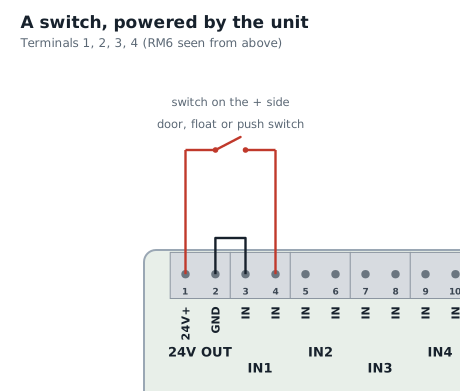
- One switch wire to terminal 1 (24V OUT 24V+).
- The other switch wire to terminal 4 (IN1).
- A short wire from terminal 3 (IN1) to terminal 2 (24V OUT GND).
IN1 shows On while the switch is closed. To make closed read Off, tick Invert in the input's settings.
A switch on the ground side
The same switch breaking the ground side instead: works just the same.
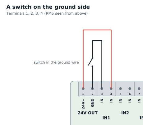
- A wire from terminal 1 (24V OUT 24V+) to terminal 4 (IN1).
- One switch wire to terminal 3 (IN1).
- The other switch wire to terminal 2 (24V OUT GND).
Works exactly like the switch on the + side: the input has no polarity, so the switch can break either side of it. Use whichever suits the wiring already there.
Several switches from one supply
Three switches sharing 24V OUT, their inputs' returns joined to one ground.
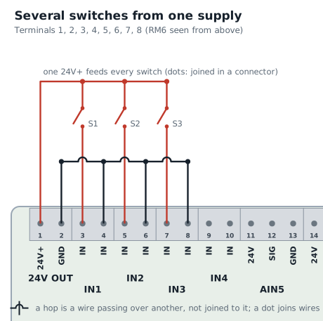
- One wire from terminal 1 (24V OUT 24V+) to a connector (a lever connector or a terminal strip), and from there to one side of every switch.
- The other side of each switch to its own input: terminal 3 (IN1), 5 (IN2), 7 (IN3).
- One wire from each input's other terminal - 4, 6 and 8 - and one from terminal 2 (24V OUT GND), all joined in a second connector.
The 24V OUT supply is fused and is meant for exactly this: it powers all four inputs' switches together, and IN4 can join the same way.
A voltage from other equipment
An alarm panel or controller output, 5-30 V AC or DC, either way round.
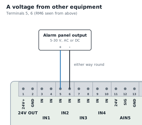
- The equipment's output + (or either wire, for AC) to terminal 5 (IN2).
- Its - (or the other wire) to terminal 6 (IN2).
- Nothing to 24V OUT: the equipment supplies the voltage.
The input is isolated from the unit, so the equipment's ground stays its own. IN2 is On whenever 5-30 V is present between the two terminals, either polarity.
Several outputs with a shared common
Three equipment outputs and their one common, joined to the inputs' other terminals.
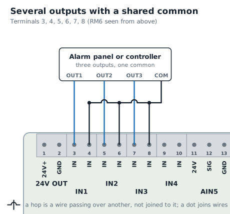
- Each output to its own input: OUT1 to terminal 3 (IN1), OUT2 to 5 (IN2), OUT3 to 7 (IN3).
- One wire from each input's other terminal - 4, 6 and 8 - joined in a connector with a wire from the equipment's common (COM, 0 V or -).
Works whether the equipment's outputs switch + (common is -) or switch - (common is +): the inputs have no polarity. 5-30 V AC or DC.
A 24 V AC signal
A thermostat call, doorbell or irrigation zone sensed from its 24 V AC transformer.
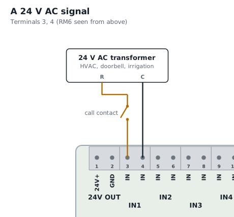
- The transformer's switched leg (through the thermostat, doorbell button or controller contact) to terminal 3 (IN1).
- The transformer's other leg (C, common) to terminal 4 (IN1).
- Nothing to 24V OUT.
IN1 is On while the contact is closed and 24 V AC reaches the input. 30 V AC is the most an input takes; never connect mains (120 or 240 V).
A 4-20 mA sensor (2-wire)
A loop-powered pressure, level or temperature transmitter on AIN5.
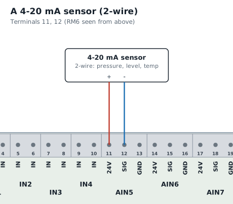
- The sensor's + to terminal 11 (AIN5 24V).
- The sensor's - to terminal 12 (AIN5 SIG).
- Terminal 13 (AIN5 GND) stays empty.
In the app, open AIN5's settings: set Signal type to 4-20 mA, then choose what the sensor measures so the reading shows in its own units (for example 4 mA = 0 psi, 20 mA = 100 psi).
A 0-10 V sensor (3-wire)
A sensor powered from the channel's 24V with a 0-10 V output, on AIN6.
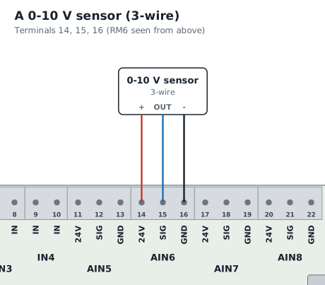
- The sensor's supply + to terminal 14 (AIN6 24V) - only if it runs on 24 V DC; otherwise power it separately and join its - to GND.
- The sensor's output to terminal 15 (AIN6 SIG).
- The sensor's - (common) to terminal 16 (AIN6 GND).
In the app, open AIN6's settings: set Signal type to 0-10 V, then choose what the sensor measures (for example 0 V = 0 %RH, 10 V = 100 %RH).
A temperature and humidity transmitter
One transmitter with two outputs, read on AIN5 and AIN6.
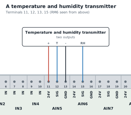
- Supply + to terminal 11 (AIN5 24V) and supply - to terminal 13 (AIN5 GND).
- The temperature output to terminal 12 (AIN5 SIG).
- The humidity output to terminal 15 (AIN6 SIG). AIN6's 24V and GND stay empty.
Set both channels' Signal type to what the transmitter outputs (0-10 V or 4-20 mA - its label says), then pick Temperature on AIN5 and Humidity on AIN6 so each reads in its own units.
DS18B20 temperature probes
Digital probes on the 1-Wire terminals; several share the same three.
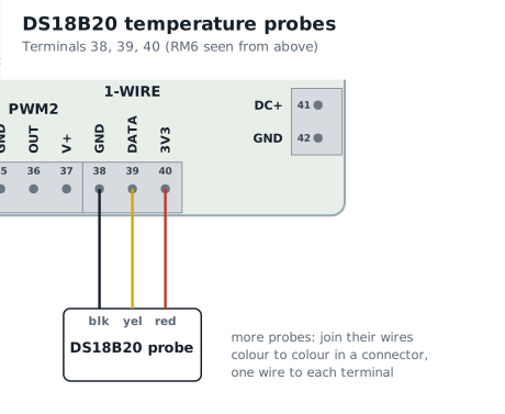
- Black (ground) to terminal 38 (1-WIRE GND).
- Yellow (data) to terminal 39 (1-WIRE DATA).
- Red (power) to terminal 40 (1-WIRE 3V3).
- For more probes, join their wires colour to colour in three connectors, and run one wire from each connector to its terminal.
Each probe appears in the app by itself as Temperature 1, 2 and so on within about 30 seconds, and keeps its number for good. To tell them apart, hold one in your hand: its reading climbs.
An LED strip or fan on PWM
A 12 V LED strip or DC fan dimmed by PWM1, on your own supply.
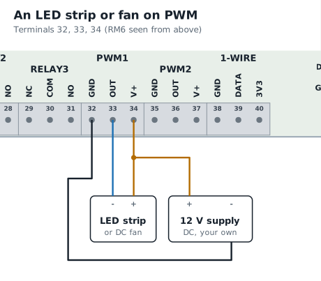
- Your supply's + to terminal 34 (PWM1 V+), and the strip's + to the same terminal.
- The strip's - to terminal 33 (PWM1 OUT).
- Your supply's - to terminal 32 (PWM1 GND).
Up to 24 V and 1 A per output. In the app PWM1 has a switch and, while it is on, a 1-100 % level slider. The unit does not power the strip: the supply is yours.
A relay pressing a button
RELAY1 across a garage door opener's push-button terminals.
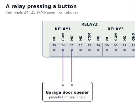
- One of the opener's push-button wires to terminal 24 (RELAY1 COM).
- The other to terminal 25 (RELAY1 NO).
- Leave the opener's own wall button where it is: the relay is wired alongside it.
In RELAY1's settings, tick Momentary and set Hold for to about 1 second: the row then shows a Pulse button that presses the opener's button for you.
A relay switching a 24 V AC valve
RELAY2 switching an irrigation or water valve from its transformer.
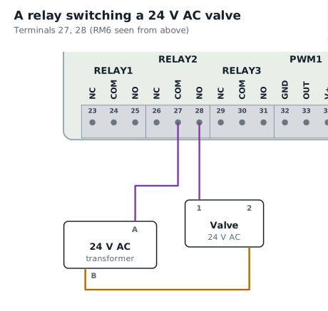
- One transformer leg to terminal 27 (RELAY2 COM).
- Terminal 28 (RELAY2 NO) to one valve wire.
- The valve's other wire back to the transformer's other leg.
The valve opens while RELAY2 is on. Relays switch up to 30 V AC or DC (1 A at 24 V DC, 0.5 A AC): never mains. For a valve that must close if the unit loses power, this is the right way round.
Powering the unit
An 8-30 V DC supply on the power terminals, or USB-C.
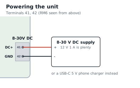
- The supply's + to terminal 41 (DC+).
- The supply's - to terminal 42 (GND).
8 to 30 V DC: a 12 V or 24 V adapter, or an alarm panel's auxiliary output. The unit draws about 10 W at most. A USB-C phone charger works instead; use one or the other, not both.